Module USB CH376 + SD

Module USB CH376 + SD Yêu thích
0 Đánh giá
Giá: 330,000 đ
Giao hàng toàn quốc
Giá sản phẩm chưa bao gồm VAT
Trạng thái : Hết hàng
LIÊN HỆ MUA HÀNG
Tổng đài: 0972.84.11.66 - Email: sale.banlinhkien@gmail.com
Sản phẩm tương tự
Product Description:
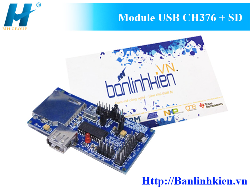
CH376 is used as file manage control chip, used to MCU system read/write file in USB Flash Drive.
Feature:
- CH376 chip curing FAT file system, File is simple, rapid.
- Support U disk, USB hard drives, USB flash drives and USB card reader USB storage devices, etc.
- Support SD card, HC-SD card and protocol-compatible MMC, TF Card
- Support a variety of communication interfaces: an 8-bit parallel port, SPI interface, and asynchronous serial
- Compatibility:Device mode compatible with CH372, host mode compatible with CH375
- Module Size: 50mm × 34mm
Package includes:
- 1X CH376 USB MODULE

- CH376


Note:
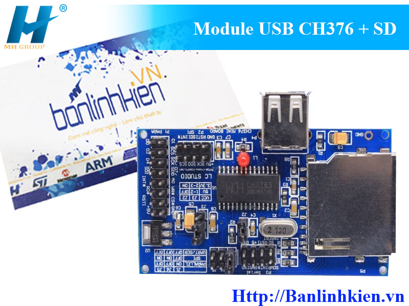
Evaluation board in the main device U1 is CH376S chip, but the figure is some signal named CH375 or CH374.
Crystal X1 is standard 12MHz, USB host USB devices demand higher than the frequency accuracy, X1 is less than the error requires 0.4 ‰, essentially to meet the ordinary requirements of a 12MHz crystal. Strongly recommended to shorten the length of lead-related in order to reduce interference.
C4 is used for decoupling the internal power node to reduce the USB transfer process EMI, 4700pF to 0.1uF, can use an ordinary 103 Chip Capacitors 0.01uF.
P4 is the USB port, USB HOST host can be used both ways, can also be used for USB DEVICE mode devices, resistors R1 to limit the output current to an external USB device, to avoid the U disk and other USB devices just insert the power supply voltage caused by short-term decline, and even lead to CH376 or microcontroller reset or non-normal internal RAM data error. If a USB external hard drive, then replace the resistor R1 should be smaller inductor DC resistance, or the other with a 5V power supply to provide greater direct current (500mA or more) to the external hard drive. In addition, USB-HOST socket power supply decoupling capacitor C9 capacity can not be too small, some large capacity (should be greater than 100μF) reduces just insert the USB device when the power supply voltage fluctuations.
P5 is the SD card socket, you can access standard-size SD card, and other specifications of the SD card may need to convert additional seat. Resistor R3 is used to limit the output current to an external SD card, just insert the SD card to avoid the supply voltage caused by short-term decline.
P1 is a signal 8-bit parallel port for connecting the microcontroller parallel port, parallel port, including the necessary signals D0-D7, A0, RD #, WR #, CS # and GND, while the INT # is optional.
P2 is the SPI serial signal port for connecting the microcontroller SPI interface, SPI, including the necessary signals SCS, SCK, SDI, SDO and GND, while the INT # is optional.
P3 signal is asynchronous serial port for connection to single-chip asynchronous serial port, asynchronous serial port, including the necessary signals RXD, TXD and GND, while the INT # is optional. P3 also provides a write-protected SD card and plug the state SDINSERT SDWP signal line.
The P1, P2, P3 communications port can also be provided from an external 5V power supply to the evaluation board, as well as to the RSTI is CH376 provides an optional hardware reset signal, the circuit if the actual product in μP Supervisory Circuits, then should CH376 and the microcontroller provides a reset signal is the same. Note, this kit should be as short as possible between the microcontroller and the signal line length no longer than 20cm, otherwise need to use a signal interval a dedicated ground cable.
J3 is used to select CH376 chip voltage, short 1-2 pin when the voltage is 5V, pin 2-3 short when 3.3V voltage. The default is 5V voltage, but when the MCU operating voltage is equal to or less than 3.3V and 3.3V voltage can be selected for the CH376. When CH376 chip operating voltage of 5V, J2 must be disconnected when the CH376 chip when the voltage is 3.3V, J2 must be short.
J1, J5 and J6 is used after power-on or hardware reset selection CH376 communication interface with the microcontroller:
If the short J1, J5 off, J6 off, then the 8-bit parallel port;
If you disconnect J1, J5 shorted, J6 shorted, then the SPI interface;
If you disconnect J1, J5 off, J6 off, then the asynchronous serial port.
Some examples of programs may use single-chip serial debugging output status information, if you need to display the monitoring information by the microcontroller through the serial RS232 level conversion using the serial port to connect to the computer monitor / debugger software to view. If CH375 evaluation board, then J2 can be connected to the computer serial port; If the computer does the serial port or serial port is already occupied by other equipment, then the USB to serial port emulation chip CH341 supplies.
CH375 work on internal device evaluation board 5V supply voltage, resistance must be added and removed 3.3V regulator R0 D4, operates from a 3.3V supply voltage, the regulator must be added and removed D4 resistance R0. The default is 5V power supply.CH376 USB development board / evaluation board module, with SD card connector
65元
Evaluation board in the main device U1 is CH376S chip, but the figure is some signal named CH375 or CH374.
Crystal X1 is standard 12MHz, USB host USB devices demand higher than the frequency accuracy, X1 is less than the error requires 0.4 ‰, essentially to meet the ordinary requirements of a 12MHz crystal. Strongly recommended to shorten the length of lead-related in order to reduce interference.
C4 is used for decoupling the internal power node to reduce the USB transfer process EMI, 4700pF to 0.1uF, can use an ordinary 103 Chip Capacitors 0.01uF.
P4 is the USB port, USB HOST host can be used both ways, can also be used for USB DEVICE mode devices, resistors R1 to limit the output current to an external USB device, to avoid the U disk and other USB devices just insert the power supply voltage caused by short-term decline, and even lead to CH376 or microcontroller reset or non-normal internal RAM data error. If a USB external hard drive, then replace the resistor R1 should be smaller inductor DC resistance, or the other with a 5V power supply to provide greater direct current (500mA or more) to the external hard drive. In addition, USB-HOST socket power supply decoupling capacitor C9 capacity can not be too small, some large capacity (should be greater than 100μF) reduces just insert the USB device when the power supply voltage fluctuations.
P5 is the SD card socket, you can access standard-size SD card, and other specifications of the SD card may need to convert additional seat. Resistor R3 is used to limit the output current to an external SD card, just insert the SD card to avoid the supply voltage caused by short-term decline.
P1 is a signal 8-bit parallel port for connecting the microcontroller parallel port, parallel port, including the necessary signals D0-D7, A0, RD #, WR #, CS # and GND, while the INT # is optional.
P2 is the SPI serial signal port for connecting the microcontroller SPI interface, SPI, including the necessary signals SCS, SCK, SDI, SDO and GND, while the INT # is optional.
P3 signal is asynchronous serial port for connection to single-chip asynchronous serial port, asynchronous serial port, including the necessary signals RXD, TXD and GND, while the INT # is optional. P3 also provides a write-protected SD card and plug the state SDINSERT SDWP signal line.
The P1, P2, P3 communications port can also be provided from an external 5V power supply to the evaluation board, as well as to the RSTI is CH376 provides an optional hardware reset signal, the circuit if the actual product in μP Supervisory Circuits, then should CH376 and the microcontroller provides a reset signal is the same. Note, this kit should be as short as possible between the microcontroller and the signal line length no longer than 20cm, otherwise need to use a signal interval a dedicated ground cable.
J3 is used to select CH376 chip voltage, short 1-2 pin when the voltage is 5V, pin 2-3 short when 3.3V voltage. The default is 5V voltage, but when the MCU operating voltage is equal to or less than 3.3V and 3.3V voltage can be selected for the CH376. When CH376 chip operating voltage of 5V, J2 must be disconnected when the CH376 chip when the voltage is 3.3V, J2 must be short.
J1, J5 and J6 is used after power-on or hardware reset selection CH376 communication interface with the microcontroller:
If the short J1, J5 off, J6 off, then the 8-bit parallel port;
If you disconnect J1, J5 shorted, J6 shorted, then the SPI interface;
If you disconnect J1, J5 off, J6 off, then the asynchronous serial port.
Some examples of programs may use single-chip serial debugging output status information, if you need to display the monitoring information by the microcontroller through the serial RS232 level conversion using the serial port to connect to the computer monitor / debugger software to view. If CH375 evaluation board, then J2 can be connected to the computer serial port; If the computer does the serial port or serial port is already occupied by other equipment, then the USB to serial port emulation chip CH341 supplies.
CH375 work on internal device evaluation board 5V supply voltage, resistance must be added and removed 3.3V regulator R0 D4, operates from a 3.3V supply voltage, the regulator must be added and removed D4 resistance R0. The default is 5V power supply.


